Hyperion Coordinate Systems#
Rotation Coordinate Systems#
Within hyperion coordinates are expressed both in requests to Hyperion, in commands issued to hardware, and in the output files sent to downstream analysis.

Within requests to Hyperion, the requested rotations are defined with respect to a fixed coordinate system, that is defined to be the same for all installations and the intention is that this should be the same as that defined by the nexus file format when all axes are in their positive orientations. Thus the same request made across different deployments of Hyperion should result in the same physical motion regardless of the coordinate space conventions of the underlying hardware.
In the RotationScan parameter class scan_width_deg is defined to always be positive and the direction is
defined by rotation_direction which can be POSITIVE or NEGATIVE
The coordinate systems of the underlying hardware may differ from the request. At Diamond traditionally the omega
axis is implemented to be in the opposite direction, therefore the commands sent to the hardware are transformed and
the omega_flip flag controls this behaviour, which by default is set to True as this is
generally expected to be required for the beamlines here.
In the Nexus output file, there is provision for describing the choice of axis orientations in the nexus file, and
the omega_flip parameter affects the omega axis description in /entry/sample/transformations/omega.
This is especially important as if PCAP position capture is enabled then referenced data files will contain positions
with respect to this axis.
Gridscan Coordinate System#
The diagram below shows how the coordinate system used in the 3D gridscan relates to the beam and sample loop. The blue arrows indicate the direction of the beam. The red grids represent the grids used during the scan.
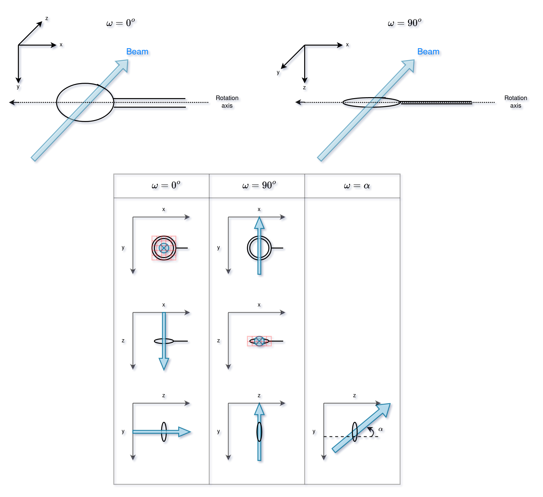
Motors Coordinate System#
The diagram below shows the x,y,z directions of the smargon motor coordinate system. The smargon y, z axes change with the \(\omega\). x,y,z are measured in millimetres.
The pin runs from -ve x to +ve x
y is +ve towards the ceiling when \(\omega = 0\).
z is +ve towards the detector/away from the oav and parallel to the beam when \(\omega = 0\).
The x and y coordinates of the image are also shown, the image feed has x from left to right, y from top to bottom, with the pin to the right of the image.
ω rotates from the y axis at \(\omega = 0\) (the floor to ceiling).
\(\omega = 0\)

\(\omega = \alpha\)

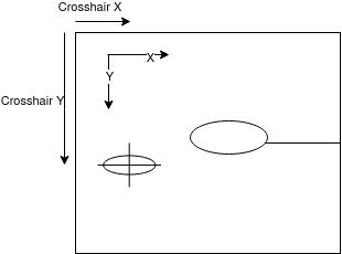
OAV Image Coordinate System#
In the OAV image the below coordinate system is used (with units in pixels).
Conversion Between OAV Image and Smargon#
At \(\omega = 0\), \(x\) and \(y\) in the camera are antiparallel to \(x\) and \(y\) in the smargon. \(y\) in the camera are is parallel to \(z\) of the smargon at \(x\) = \(\frac{\pi}{2}\). Then to convert from the camera to smargon coordinate systems we map
\(x_\text{smargon} = -x, \quad y_\text{smargon} = -y\cos(\omega),\quad z_\text{smargon} = y sin(\omega).\)